Zero1541
November 15, 2020
Categories: retro computing hardware
Tags: commodore vic20 raspberrypi
Background
Currently the oldest computer I have is a Commodore VIC 20, a quaint little computer that came out in 1981 with an amazing 5 kilobytes of RAM, 16 colors, and three voice channels all in a breadbin case. Of course the following year Commodore would come out with the much, much more successful Commodore 64, but the VIC 20 is still a fun machine with interesting quirks to explore. I got this VIC from my friend’s dad, and it seemed to spend most of its life tucked away in the original packaging and still works almost perfectly. Though because it didn’t see too much use, it only has the included Datasette for loading/saving things to an audio cassette. Now the Datasette is rather slow when it comes to transferring data, but it also has the slightly annoying feature of not having a dedicated audio in/out jack that other computers of the era used, which means I can’t just plug it into my phone and play an audio file. For serious work, you would have wanted to get a floppy disk drive: Commodore VIC-1540. This 5 1/4in floppy disk drive would have been a huge upgrade in speed and storage capability. It would also spawn a line of floppy drives (dropping the VIC part of the name) that would be used with all the future Commodore 8-bit computers.
Now really, having a 1540 (or any of the successor drives) wouldn’t help me too much today. I would still have to get data onto a 5 1/4in floppy disk before I could then load it on the VIC, and I don’t have a way to do that at the moment. But it turns out there are many modern solutions to this problem that allow you to put everything on a SD card which then is used by a device emulating one of Commodore’s floppy disk drives. Initially I looked into making a version of the popular SD2IEC devices that was designed by retrohax as they provided all the files needed to get the boards made and they are a handy small thing that could be mounted inside the case (should you be ok with drilling holes or slots in it). So I jumped in, ordering a couple boards and smattering of parts to assemble them. Looking back, this was a project that was way above my skill level, as all but one LED is a surface mount part, and being a small board everything is close together. I could never quite get any of the three boards I assembled to get working, so I turned to another solution.
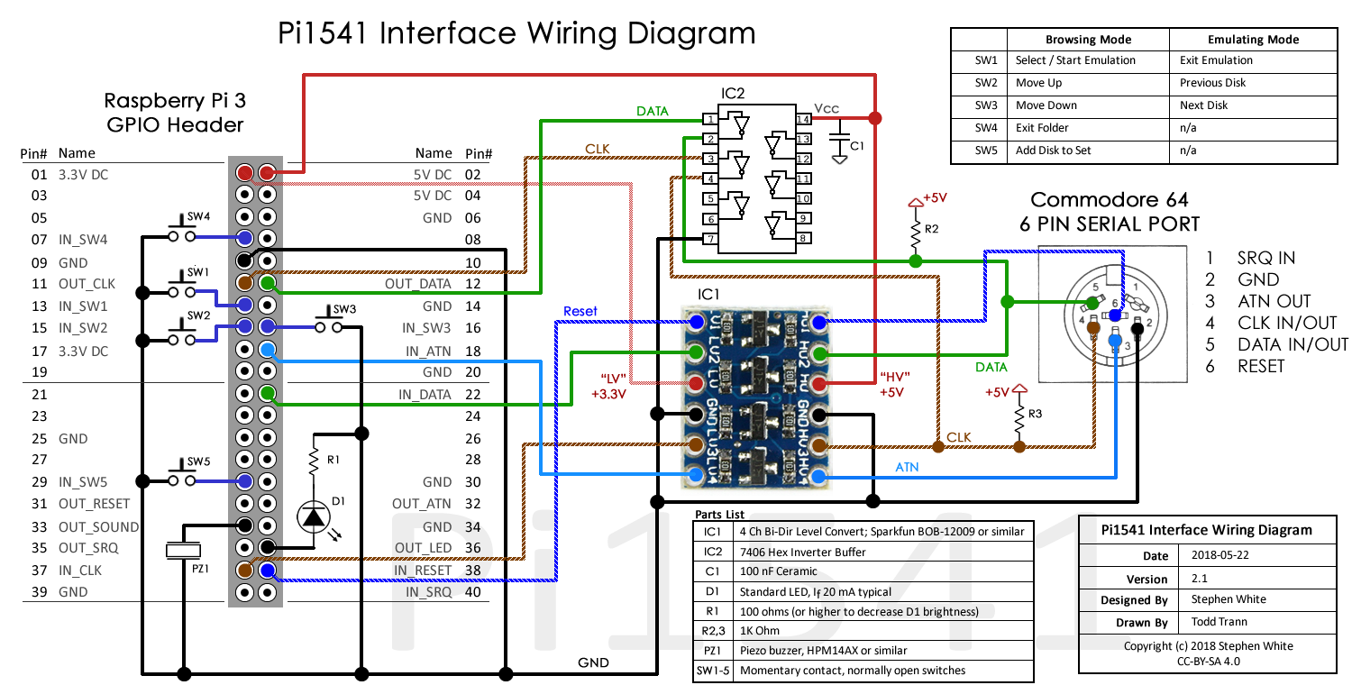
Another emulator is the Pi1541, which uses a Raspberry Pi and a simple circuit. One of the biggest benefits to me is that building a board myself would be greatly simplified as it can simply be a ‘hat’ for a Raspberry Pi. It also is quite a bit more powerful than a SD2IEC as it can do everything a real 1541 can do (such as run software directly on it) that the SD2IEC doesn’t have the processing power and memory for. A couple of people have put together ‘hats’ that you can either buy out right or build yourself, though all of these are designed to sit on top of a Pi 2 or 3 model B. I was looking for something that would fit on top of a Raspberry Pi Zero, as it would look more like the drive it was emulating. I did find an example of what I was looking for, but it was missing one feature that I also wanted: the ability to daisy chain more devices off it. Original Commodore drives (and printers) would have multiple IEC ports so you could chain them all together to one host. If I wanted to be able to use this with other hardware, I would need this ability.
So I sat down and designed a board.
Board Design
Let me preface this with: I am not an electrical engineer, at best I am a hobbiest that knows just enough to not let out too much magic smoke. For the schematic, there is a good starting point on the Pi1541 website though I ended up using the work of Christian G as there was a KiCAD project that I could start off of. KiCAD itself is a very complex piece of software to use, as it is a professional grade tool and I am probably missing out on a lot of things it can do for me. For putting together small, two layer boards, I know just enough to get it to do what I want.
Besides shrinking down everything to fit about the size of a Pi Zero, I also wanted to change out the logic level voltage conversion. The Pi1541 project suggests using an easy to find I2C Bi-Directional Logic Level Converter (Adafruit and Sparkfun offer identical products), but does warn that using this method will put some strain on the Raspberry Pi as it will have to sink the current of signals sent along the IEC bus. A better solution would be to use a converter that is designed for this situation (specifically an open-drain) and it just so happens the TXS0108 was made for this. Now before I mentioned that the SD2IEC I tried to make was all surface mount parts, this time I was going to go with a single surface mount part and the rest all through-hole. I would have gone all through-hole, but the TXS0108 only comes in surface mount packages and it just so happens it also really helped with keeping the board size small.
I also kept Christian’s small solder bridge jumpers so the same board could be built for either using with multiple devices or as the only IEC device. This also is handy for setting I2C signals to match whatever screen you may use, again all without having to design a whole new board. After a couple of attempts to route everything, I finally had something I figured was correct enough to send off for production.
Board Bring Up
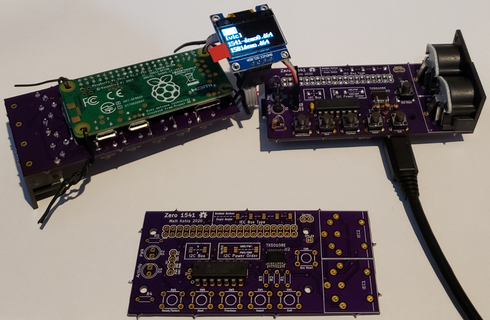
A couple of weeks later, and I had purple boards from OSHPark and a box of parts from DigiKey. Assembly was a breeze, but once I loaded up a SD card and powered on the Pi I didn’t get any signs of life. First I double checked the SD card was formatted right, using different OSes just in case, and still nothing. Then with a second partially finished board I tried the same card and noticed the LCD would come up. Here I realized I got the silkscreen wrong on some of the solder jumpers, mixing the SINGLE and MULTI Device bridges, which meant the I2C signals going to the screen would also be sent to the IEC bus and vice versa. Fixing the solder jumpers on the finished board didn’t give me any life though, and the LCD was still blank.
![]()
PCB. Note silkscreen errors and incorrect button wiring on this revision
![]()
Probing around with a multimeter, I realized the switches I used did not match the footprint I used in the board design. While they were the same size and physically fit in the holes, they connected different sides of the button so each button was always pressed. This meant the reset line was always pulled down so the Pi1541 was always rebooting, so no life on the screen. Some short bodges later, and snipping of a leg on each button later, and the finished board came to life. All the buttons worked as expected too, and I now had a way to get files to and from my VIC.
Using
Setup probably isn’t too much different from that of a real 1541, you simply plug power (a micro USB) and IEC cable into the Pi1541, then the same IEC cable into the VIC. Instead of a floppy disk, you put a SD card in (before powering it up) and as far as the VIC (or any other device on the IEC bus) is concerned, this is a floppy drive. The buttons on it make it easy to change directories and load/unload a disk image, though using the SD2IEC FileBrowser software you can do the same from your computer.
Overall I am really happy with how it turned out. I still need to design a case for it, probably a small 1541 or maybe a 1581. But now I can put all the VIC 20 software on a SD card and try it out on a real computer, even though I mainly use it to write new programs on my main machine and then run it on the VIC.
If you want to make your own version of my Zero1541, you can download the KiCAD files from my git repo here. (Though I haven’t re-routed the buttons yet as of posting this)